Experiment of The Month
Conical Anamorphosis

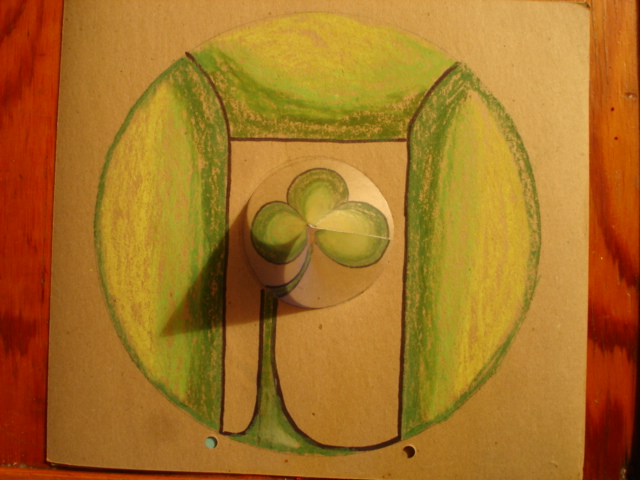
Jeffrey Moser was taking the Physics 231 honors seminar when he did this project for his final paper. He became interested in an artist's work which produced images like the one at the right.
At first glance you see a three-leaf clover with a kink in the stem, surrounded by a green arbor. A second look suggests that the central region is shiny, like a mirror. The shadow and a faint seam suggest that the mirror is conical in shape. It is.
The mirror image of the cone-shadow suggests (correctly) that the three-leaf clover is the mirror image of the arbor. The phrase "conical anamorphosis" is ment to suggest the transformation of one image into another, using conical geometry.
To see dramatically the effect of the transformation, view the four pictures below, taken as the reflecting cone is slid into position.
Mr. Moser worked out one of the mathematical transformations for this construction. We can see how the ideas go using graphical considerations.
The first fact to note is that a plane (flat) mirror produces a very simple image when an object is placed in front of it. The image is undistorted, and using our binocular vision, we can see that it lies behind the mirror surface. The distance from the image to the mirror surface is the same as the distance from the object to the mirror surface. If you move your head, you can see different aspects of the image, but the image is always directly across the mirror surface from the object.
 The sketch at the right shows an eye looking down at a plane, tilted, mirror. The mirror forms the image of an arrow. The rays of light that travel from the arrow to the eye are those which strike the mirror at the "correct" angle. The "correct" angle of incidence results in a vertical reflected ray. Other rays simply miss the eye, unless the eye moves over to capture them.
The mirror is tilted at 60 degrees to the horizontal, the same angle as the one Mr. Moser's cone makes with the horizontal. The dashed line is a line perpendicular to the mirror surface. It helps us to decide on the location and orientation of the image. The distance to the mirror is measured parallel to that dashed line.
Note that the light which reaches the eye travels upward at all times. The arrow could be sitting on a piece of white paper and we would still see the same image. This means that the mirror is longer than it needs to be. In no case does it need to go lower than the arrow itself.
Finally, note that moving the object to the left causes the rays which meet the eye to come from higher up on the mirror. When they move up, the eye sees the image move to the right.
The tip of the object is closest to the mirror surface, and so the tip of the image is closest to the mirror surface. (This leads to the confusing statement that mirrors change right for left.) The viewer sees an arrow tilted at an angle, so that the arrow appears shorter in length.

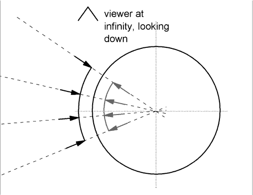
The cone mirror is more complicated. For a single arrow, it shows a tilted surface that can be analyzed as above. But for a family of arrows, the nature of the image takes more thought. To take a small step, consider the image of four arrows in a cylindrical (not conical) mirror. The arrows are carefully chosen so that each points along a radius of the cylinder. The arrows and their images are shown in the figure at the right.
Each radial line is perpendicular to the surface of the mirror, making it easier to locate the image behind the surface. For the object, the tip of each arrow is closer to the mirror than the tail, and the same is true of the image
With these arrows arranged as shown, with their tips on an arc, it is easy to imagine the image of the arc. (It is important that the arc is centered on the center of the cylindrical mirror.) The image arc is shorter, subtending the same angle of the object. The image arc is the same distance from the mirror as the object arc.

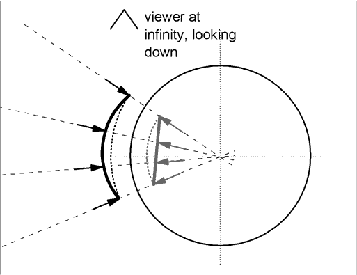
Objects with other shapes grow increasingly difficult to imagine our way to the image, but we can do one more example; a straight line. In order for the image to be a straight line, the object must be deformed from a straight line. (A straight line object would produce an image with tighter curvature - smaller radius of curvature - than the arc.)
We start by drawing the line that we desire for the image. Then we construct an arc on the image side of the mirror, with center at the center of the mirror, and with its ends touching the ends of the straight line. We know from the previous example how to construct an object arc which produces this image.
We measure the distance between the image straight line and the image arc, along each radial line in the figure. This same distance must be the distance between the object for the straight line and the object that produced the simple arc. The result is sketched, with the arrow tips defining the arcs for ease of thinking.
The reader is invited to sketch the object shape which produces a concave line for an image.
If the radius of the cylindrical mirror is decreased, the same curved object will produce an image which is farther from the mirror surface. The arc associated with that image will have a smaller radius, Ra. The maximum separation between the straight image line and its arc is given by
h = Ra - (1/2)(4Ra2 - C2)(1/2)
where C is the length of the straight line. This requires a change in the shape of the object that will successfully create the image of the straight line in the mirror. As Ra gets smaller, h gets larger, so the object must bend further away from the original arc.
The problem becomes more difficult when the cylinder is converted to a cone. As with the cylinder, the object creates an image whose shape depends on the radius of the mirror. For the cone the radius changes, becoming smaller nearer the apex. As indicated in the first figure, more distant objects will be imaged closer to the apex, for an eye looking straight down.
Distant objects will be imaged to the eye by a curved mirror with smaller radius. Distant objects must distort more in order to create the desired image.


